Call Activities
BPMN Call Activities ( )
A BPMN Call Activity is used to call a process defined in a different diagram. The called activity runs as part of the calling process instance.
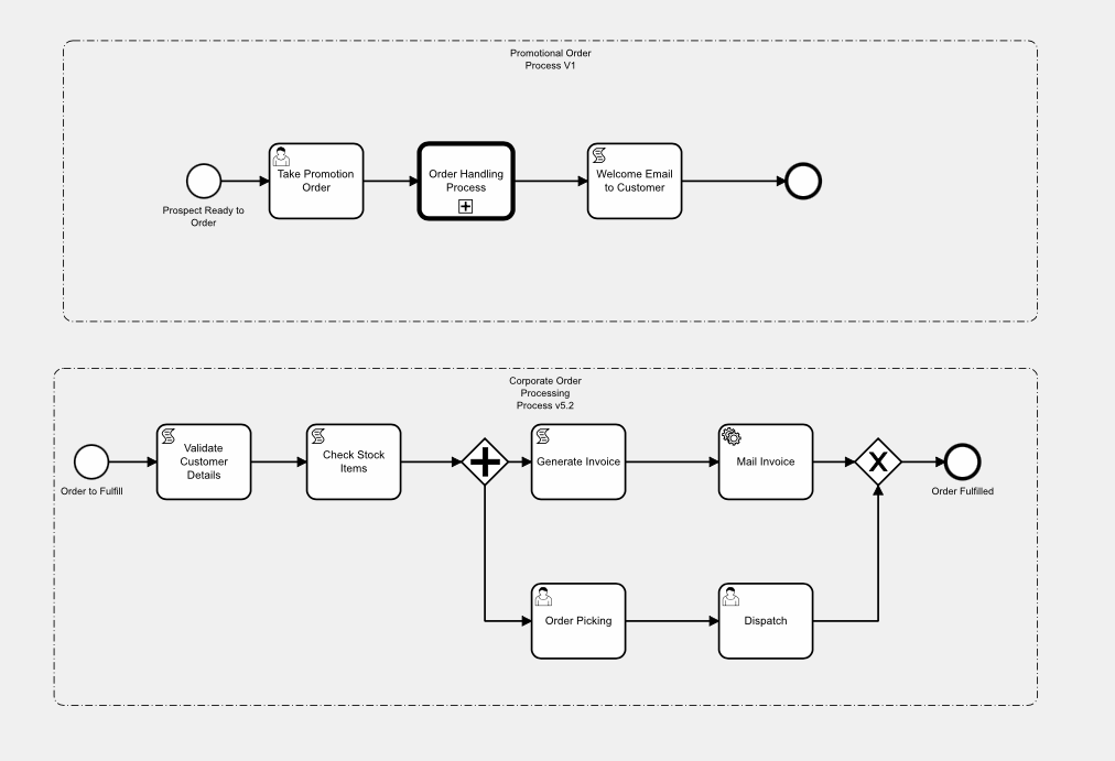
In this example, above, there is an existing process diagram for the order processing and fulfillment process (‘order to cash’). The Marketing Department want to create a workflow-based application for a promotion that they are running, which targets a set of customers, makes them an offer, and then fulfills those orders. The promotion has its own APEX application, and then it ‘drops’ any orders it generates into the standard, corporate ‘order-to-cash’ process. The Marketing Department don’t want to have to include the details of the ‘order-to-cash’ process into their promotion process diagram, as this is already defined in another diagram and is controlled by the Operations Department. They can implement this in Flows for APEX by including the ‘order-to-cash’ process as a BPMN call activity in their marketing promotion process.
Adding a Call Activity to the Calling Process Model.
First of all, build the diagram that you want to call if you haven’t already.
Add a Call Activity into your BPMN diagram by adding a task ( the symbol). Then, using the spanner tool , convert the task to a Call Activity ( ).
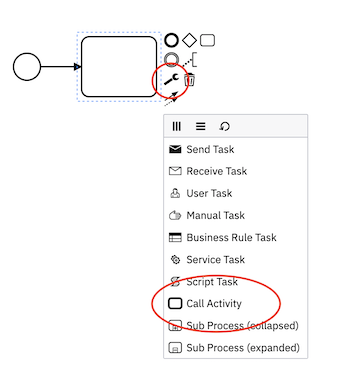
Name. On the Modeler properties panel, in the General section , give your call activity a descriptive name.
ID. By default, this generates a random name like ‘‘Activity_0d5gtyh”. You can change this to something more descriptive, but it should be short and not contain any spaces.
To configure a Call Activity, use the properties panel in the Flow Modeler. While setting parameters, the Flow Modeler can use meta-data already stored in Flows for APEX to set, for example, the model name or the required Input and Output Variables, or they can be entered manually. The Input Method pull down can be changed from Manual to ‘use meta-data’, as required.
The following properties need to be set:
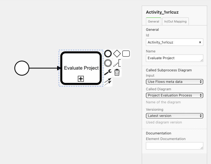
- Diagram to be Called
- Diagram Version to be called. Version information is evaluated when the process instance is created, not when the diagram is called. Version selection can be based on either:
- A Specific Version, which you must then enter, or
- The Latest Version, which would select the current
releasedversion of the model, or failing that, adraftmodel with version of0.
*note: as the diagram version is evaluated at process creation, the versioning does not get reset when a process instance is reset. While not a problem in production running, during development when you are refining your diagrams, remember that reseting a process instance will not change the diagram being called. You must start a new process instance to get the new digram version. *
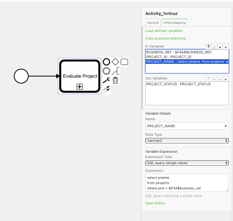
- In-Variables. These are Process Variables or values from the Calling process that you want to be created in the Called process when it is entered. In-Variables can be set using any of the methods used in variable expressions. In Variables are created in the scope of the Called Process. Any expressions or variables copied will refer to variables in the Calling process.
- Out-Variables. These are Process Variables or values from the Called process that you want to be returned to the Calling process when the called process is complete. Out-Variables can be set using any of the methods used in variable expressions. Out Variables are created in the scope of the Calling Process. Any expressions or variables copied will refer to variables in the Called process.
Two helper functions exist (usually colored in green on the properties panel) to help specification.
- Load Defined Variables. If the Called diagram has specified its required Input and Output Variables to document its interface, the required input and output variables will be loaded into the In Variables and Out Variables regions, ready for you to complete.
- Copy Business Reference. The Business Reference for a process is usually the Primary Key of the subject record in the system of reference. Clicking this will add the Business_ref of the calling process to be copied to the business_ref of the called diagram.
Business Ref in Called Process. Sometimes the Business Ref will be the same in both calling and called processes – typically when the called diagram is just a decomposition of a larger process into sub-processes. On other occasions, the Business Ref of the Called Process might be different to the Business ref in the calling process (for example, an inventory stocktaking process might have a business ref which is the stocktaking_event_id. If it calls a re-ordering process for each item found to need re-ordering, the business ref in the called ‘Reorder Item’ process might be the item part_number).
Variable Scoping
Process Variables are defined within the scope of a single diagram.
At runtime, and once a diagram has been called (entered) by a process instance, a diagram is given a scope. All process variables created in that diagram have that scope.
The scope of the initial diagram used by a process instance is always scope 0. The scopes of called diagrams are set to the subflow_id of the first subflow to operate in that diagram.
So a variable ‘myVar’ created in the top level diagram for a process has scope 0, and is a different process variable to the variable ‘myVar’ created in a called diagram having, for example, a scope of ‘270’.
If you are not using Call Activities, all processes are running in their top level diagrams, all with scope = ‘0’, and you don’t need to worry about scope. If you are going to use Call Activities to next your diagrams, as a developer you need to be aware of and use variable scoping.
More information about Scope is contained in the Flows for APEX Concepts section, here.
Making a Diagram Callable.
A Process Diagram should be able to be run as a process in its own right.
If you want to make a process diagram so that it can be called by a call activity in another diagram, you should take the following steps with the called diagram:
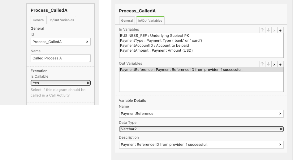
- Set the Process as Callable, using the switch in the General Tab of the diagram’s Process Object. This will make the ‘In/Out Variables’ tab appear.
- Define the Interface properties of the Process in the ‘In/Out Variables’ tab. What process variables are required to be passed into the process, and what will be returned? (This is just like defining the in and out parameters on, for example, a PL/SQL procedure specification.)
- Variable Scoping . Check that your expressions, scripts, etc., are scope aware.
Nesting of Call Activities
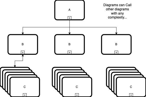
Recursion. Diagrams can be nested in any arbitrary nesting structure of any complexity, proving that you do not create recursive loops, directly or indirectly.
In the diagram below, Diagram A can call diagram B one or more times, and Diagram B can call Diagram C one or more times. However, Diagram C cannot call Diagram A or Diagram B.
Call Activity Boundary Events
Valid Types
A Call Activity can have the following boundary events attached to it:
- Interrupting Timer Boundary Event ( )
- Non-Interrupting Timer Boundary Event ( )
- Error Boundary Event (always interrupting) ( )
- Interrupting Escalation Event ( )
- Non-Interrupting Escalation Event ( )
- Interrupting Message Catch Event (Enterprise Edition only) ( )
- Non-Interrupting Message Catch Event (Enterprise Edition only) ( )
Behavior
If an interrupting ( ) boundary event fires:
- processing inside the Call Activity is terminated.
- OutVariables are not returned by the Call Activity to the calling process.
- processing continues on the interruption path back in the calling process.
If a non-interrupting ( ) boundary event fires:
- processing inside the Call Activity continues.
- new processing occurs back in the calling process on the boundary event’s forward path.
Lanes and Call Activities.
Some BPMN diagrams contain Collaboration and Participant information, i.e., they contain Lanes and Lane sets; other diagrams just contain a Process, without lane information.
Call Activities are able to handle called and calling diagrams with or without lanes.
| Calling Diagram Without Lanes | Calling Diagram With Lanes | |
|---|---|---|
| Called Diagram Without Lanes | No Lane Information is Available | All Tasks in the Called Diagram inherit the lane of the CallActivity from the Calling Diagram |
| Called Diagram With Lanes | Tasks in the Calling Diagram have no lane. Tasks from the Called Diagram contain lane information from the Called Diagram | Tasks in the Calling Diagram have lane information from the Calling Diagram. Tasks from the Called Diagram contain lane information from the Called Diagram. |
If diagrams are nested in an arbitrary, complex fashion, these rules are applied from Calling to Called diagram at runtime, and are available through the task inbox view.
Iterations and Loops (Enterprise Edition Only).
Iteration and Looping of Call Activities is not currently supported. Additionally, a sub Process that is iterated or looped cannot contain any call activities, directly or in nested sub processes.
Note for Developers and Administrators on Resetting a Process Containing Call Activities.
Resetting a process instance with the flow_reset call resets a process instance back to its created state, ready to be started with flow_start. As previously documented, this is a convenience function on the API that is often useful during development, testing, and – very occasionally– during system administration. It is NOT designed to be used widely in production systems.
With a process that has Call Activities, instance creation builds a map of the process diagrams to be used, and the call structure of those diagrams for the new instance. This is stored in the FLOW_INSTANCE_DIAGRAMS table, with one row for each diagram call that will be made. Determination of which version of a diagram will be used for the instance is made at this time. As the process instance progresses, information about the diagram-level and variable scope to be used is added to this table when the diagram is called.
As a developer / administrator / tester, be aware that if you modify the diagrams or the callActivity nesting during administration or testing, you need to create a new process instance to get these changes! If you just reset an existing process instance, you return the instance to its previous created state and the call structure will not be updated. Remembering this will save you time and frustration!